How To - Commission a Wireless I/O Module
 Updated
by
Steve Corbesero
Updated
by
Steve Corbesero
Necessary items
- Commissioner 3.4.1 or newer
Before you begin
Before commissioning a Wireless I/O Module (WIO), ensure that you have all associated materials related to the analog sensor that will interface with analog ports on the WIO.
Ensure that the analog sensor is connected correctly and verify that the IO1 or IO2 jumper is set correctly (depending on which input is being used) such that it is consistent with 4-20mA or 0-10 VDC.
Finally, please review the SWN-WIO Installation Instructions.
Workflow
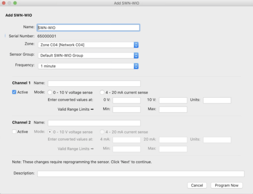
- Add WIO to the mapfile
- Click Map
- Click Add Wireless I/O
- Add via Serial Number or Wireless Discovery
- Click Next
- Once Edit SWN-WIO Dialog appears
- Enter Descriptive Name
- Choose Zone
- Choose Sensor Group
- Choose Reporting Frequency (applies to Analog Sensors only)
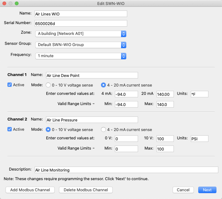
To Add Analog Sensor
- Select checkbox next to one or both channels to enable it
- Enter Channel Name
This will be the name of the datasource in SiteWorx Sense
- Select Mode (dependent on sensor type)
- Enter Converted values
This is the true value of the sensor at 0v/4mA and 10v/20mA
- Enter Units
- Enter Valid Range Limits
These are the min and max values of sensor from the specification sheet. SiteWorx uses these values to reduce noise and eliminate values outside of the max range of the sensor.
- Enter Description
- Click Program Now
Two Channel Analog Example:
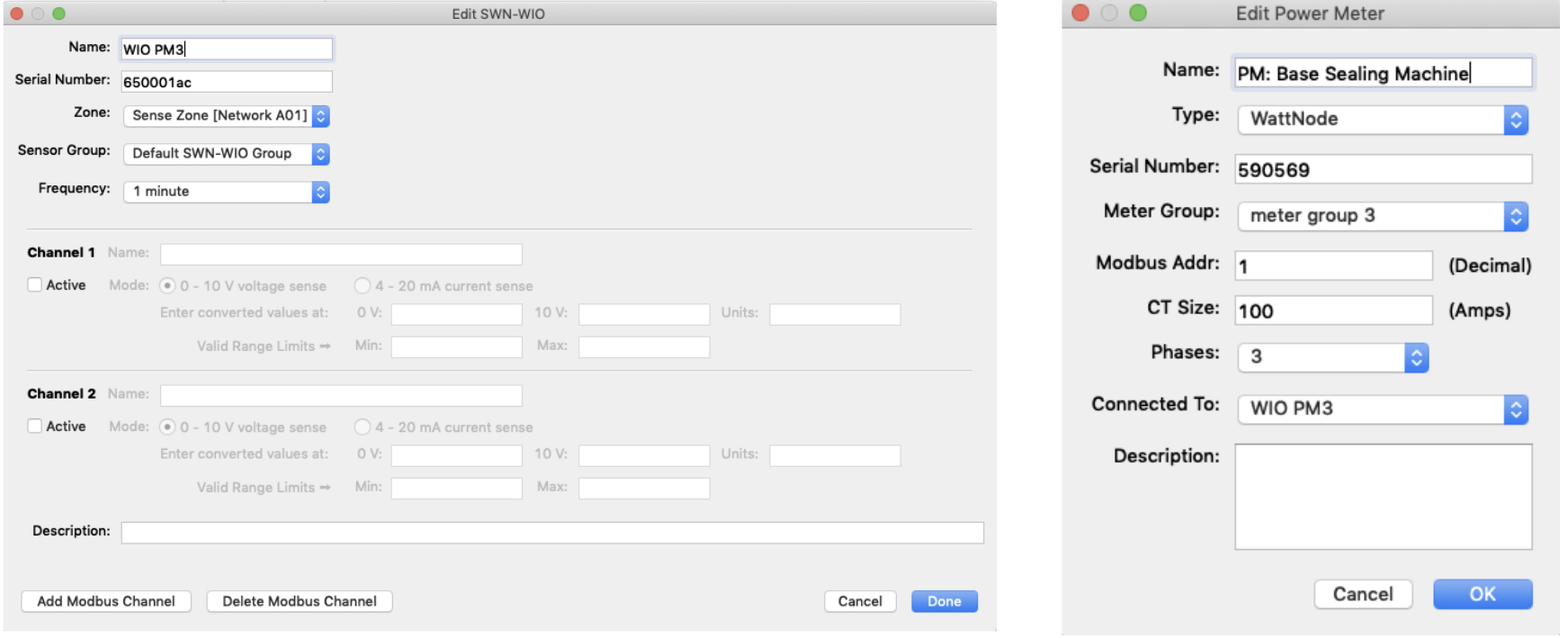
To Add Modbus CCS Power Meters
- Leave Channel 1 and Channel 2 unchecked
- DO NOT Add Modbus Channel, you will add Power Meters afterward.
- Click Program Now
- Click Done after WIO has been programmed
- Click Map
- Click Add Power Meter
- Enter Name (This will be used as the datasource name in SiteWorx Sense)
- Enter Type (Wattnode for any CCS Wattnode Power Meter)
- Enter Device’s Serial Number (if available)
- Create and Select Meter Group
- IMPORTANT: Enter Modbus Address according to each Modbus Power Meter
- On CCS Wattnode Power Meter, this will be determined by the DIP Switches
- Baud Rate should be set to 9600 on CCS Wattnode Power Meters
- Enter CT Size (in Amps)
- Select Phases (# of phases metered)
- Select Connected To (the name of the WIO the Power Meter is attached to)
- Enter Description
- Click OK
CCS Wattnode Example: